Product
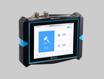
RSM-PRT(P) Low Strain Pile Integrity Tester
Dual-channel Sampling, Multi-mode Testing.
Classification:
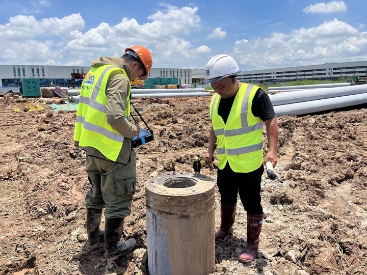
A compact, user-friendly dual-channel PIT device. Supports simultaneous signal acquisition from two acceleration sensors. Compatible with multiple low-strain testing methods, including dual-speed and transient response.
Cotnact:
Introduction
RSM-PRT(P) Low Strain Pile Integrity Tester is a newly developed dual-channel PIT device by Sinorock, featuring a refined design, intuitive interface, and easy operation. It supports simultaneous acquisition from two acceleration sensors and complies with various low-strain testing standards, including the dual-velocity and transient response methods.
Application
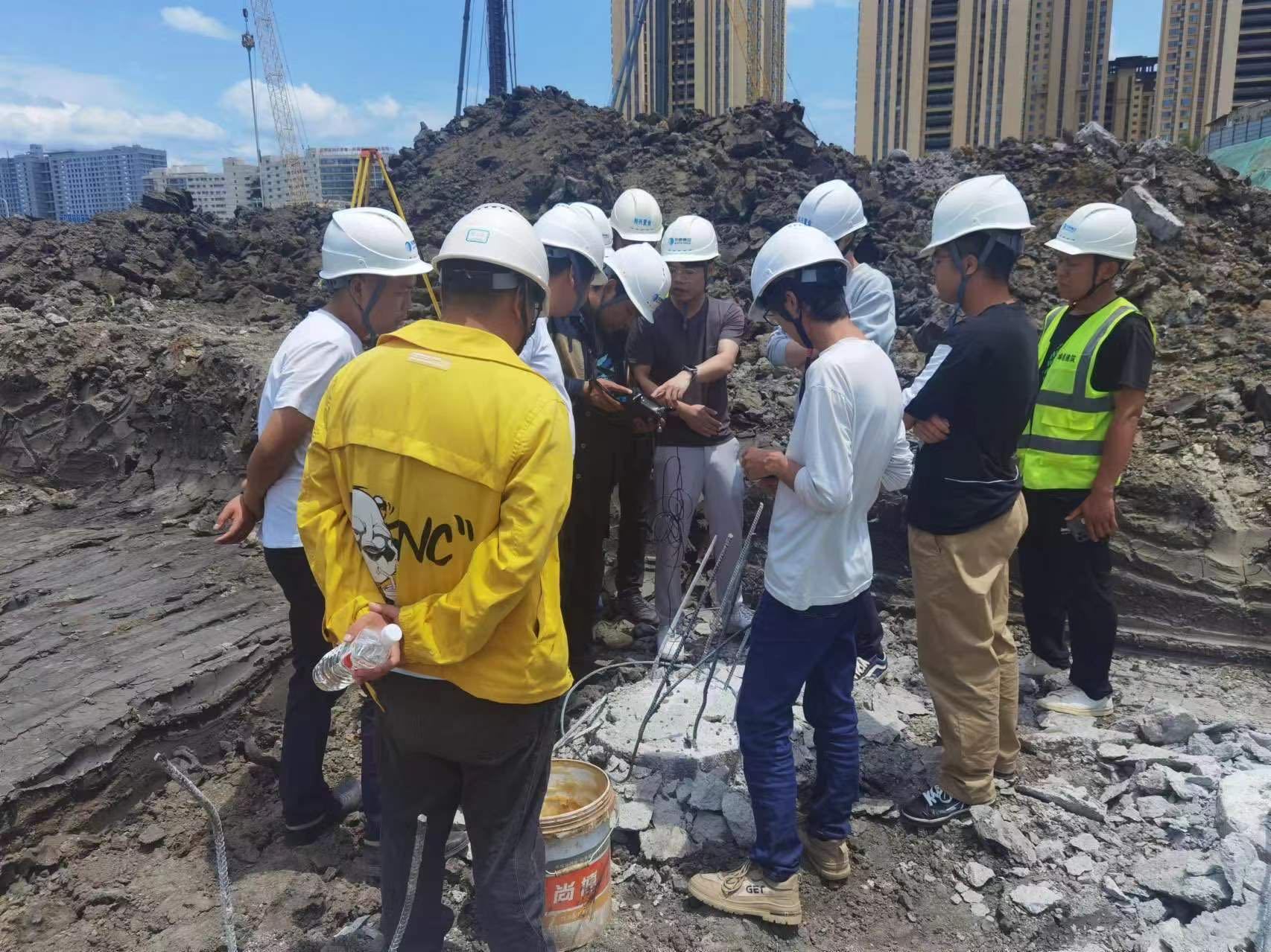
Low strain pile integrity testing by reflected wave method
Applicable standards
Standard Test Method for High Strain Dynamic Testing of Deep Foundations ASTM D4945-17
Standard Test Method for Low Strain Impact Integrity Testing of Deep Foundations ASTM D5882-16
Core advantages
Dual-channel Sampling
On-site multi-hammer superposition, signal average, real-time data storage;
Sampling interval and signal time travel curve can be adjusted randomly.
Accurate signal
Strong and weak signal acquisition without distortion;
3D correction function for shallow defect and the defect can be located accurately.
Onsite Analysis
On-site analysis can realize exponential magnification adjustment and starting position adjustment;
The defect location can be calculated, identified and corrected to 0.01m.
Industrial-grade capacitive screen
Newly upgraded industrial-grade capacitive touch screen, smooth and precise operation, adapt to strong light environment.
Large Capacity Ultra-thin Battery
9mm ultra-thin large-capacity battery, battery life ≥10h and removable.Can be equipped with a backup battery.
Newly upgraded
Engineered plastic ABS+PC.Flame retardant material, high temperature resistant design;
IP65 Dustproof and waterproof design, fearless of the extreme.
Technical Parameter
| Display method | 8.4-inch true-color LCD screen |
| Resolution | 800x600 (adjustable backlight) |
| Operation mode | Capacitive touch |
| Storage capacity | 16G electronic hard disk |
| Signal acquisition method | Wired |
| Data export method | USB |
| Master control system | Low power embedded system Basic frequency≥1GHz |
| Memory | 512M |
| Sampling Interval | 5~1000μs |
| Floating polnt magnification | 1~256 |
| Recording length | 1k |
| A/D conversion accuracy | 24-bit instantaneous floating point |
| System noise voltage | <20μV |
| Dynamic range | ≥100dB |
| Trigger level | Four-level selectable |
| Number of channels | 2 |
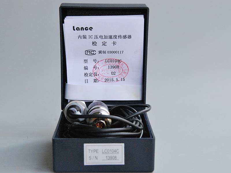
| Sensor | Piezoelectric accelerometer and speedometer |
| Sensor bandwidth | 0.5~9000 Hz |
| Operating mode | Single speed / Dual speed / Transient frequency response mode |
| Frequency bandwidth | 2~12000 Hz |
| Protection level | IP65 |
| Power supply mode | Removable lithium battery |
| Battery capacity | 12000mAh |
| Battery thickness | 9mm Battery life: ≥10h |
| Shell | Engineering |
| Plastic | ABS+PC |
| Operating temperature | -20~+55℃ |
| Dimensions | 265x200x56 mm |
| Weight | 2.0 kg (including lithium battery) |
FAQs
Q
Q1: What is the principle and testing method of the dual-velocity method in low strain testing?
+
A
A: The dual-velocity method is primarily applied to piles with partially exposed shafts. Two acceleration sensors are mounted at different heights along the pile shaft. By analyzing the time difference and waveform variations between the two sensors, the wave velocity of the pile body can be calculated. Additionally, the velocity curves obtained from both sensors can be used to derive the upward-traveling wave curve, which helps in evaluating reflections from the lower part of the pile. This technique is especially useful for testing existing structures or piles with pile caps, where conventional downward wave analysis is limited.
Q
Q2: What are the possible reasons for weak or no signal response at the pile toe in low strain testing? If caused by improper operation, how can it be avoided?
+
A
A:Insufficient impact energy – The hammer may be too light; use a heavier hammer to ensure adequate excitation.Excessive pile length – The pile may exceed the effective testing range of the low strain method.Severe or multiple defects in the pile shaft – Excessive energy loss due to defects can result in no signal from the pile toe.Impedance matching at the pile toe – When the bearing stratum impedance is close to that of the pile and bonding is good, reflections from the pile toe may not be detectable; however, any defects along the shaft can still be identified.
Operational recommendations:
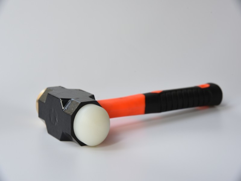
Ensure proper preparation of the pile head, select an appropriate hammer with suitable weight and material, and apply clean, decisive impacts during testing.
Q
Q3: When the waveform quality is poor and the first arrival wave is difficult to identify, is it correct to determine the first wave position using two sensors at different heights?
+
A
A: There are generally two possible reasons for this issue:
Defects within the pile itself.
Improper testing procedures, such as excessive lifting speed or the sensor striking the sonic logging tube.
When such problems occur, it is recommended to verify the issue on-site and perform re-sampling to identify the root cause, in order to avoid potential misinterpretation of the test results.
Q
Q4: If there is no clear signal from the pile toe, how should the pile toe be evaluated?
+
A
A: The absence of a distinct toe reflection can be attributed to several factors:
1.Insufficient excitation energy – A heavier hammer should be used to increase impact energy and new data should be collected. Evaluation should follow relevant standards and consider the geological conditions comprehensively.
2. Influence of pile defects – When two or more significant defects exist in the pile shaft, reflections from the pile toe are often not observed.
3. Impedance matching at the pile toe – If the impedance of the bearing stratum is close to that of the pile and the end contact is well bonded, the toe reflection may be absent. However, any shaft defects can still be detected.In some specific cases, the absence of a toe reflection is considered normal, such as:
● Extra-long piles in soft soil areas with high length-to-diameter ratios
● Strong lateral soil confinement causing rapid stress wave attenuation
● Good impedance matching between the pile shaft and the bearing stratum
● Significant cross-sectional impedance changes or gradual variation along the pile
● Joint gaps in precast pile segments impacting wave transmission
Previous Page
Next Page
Keyword:
RSM-PRT(P) Low Strain Pile Integrity Tester


